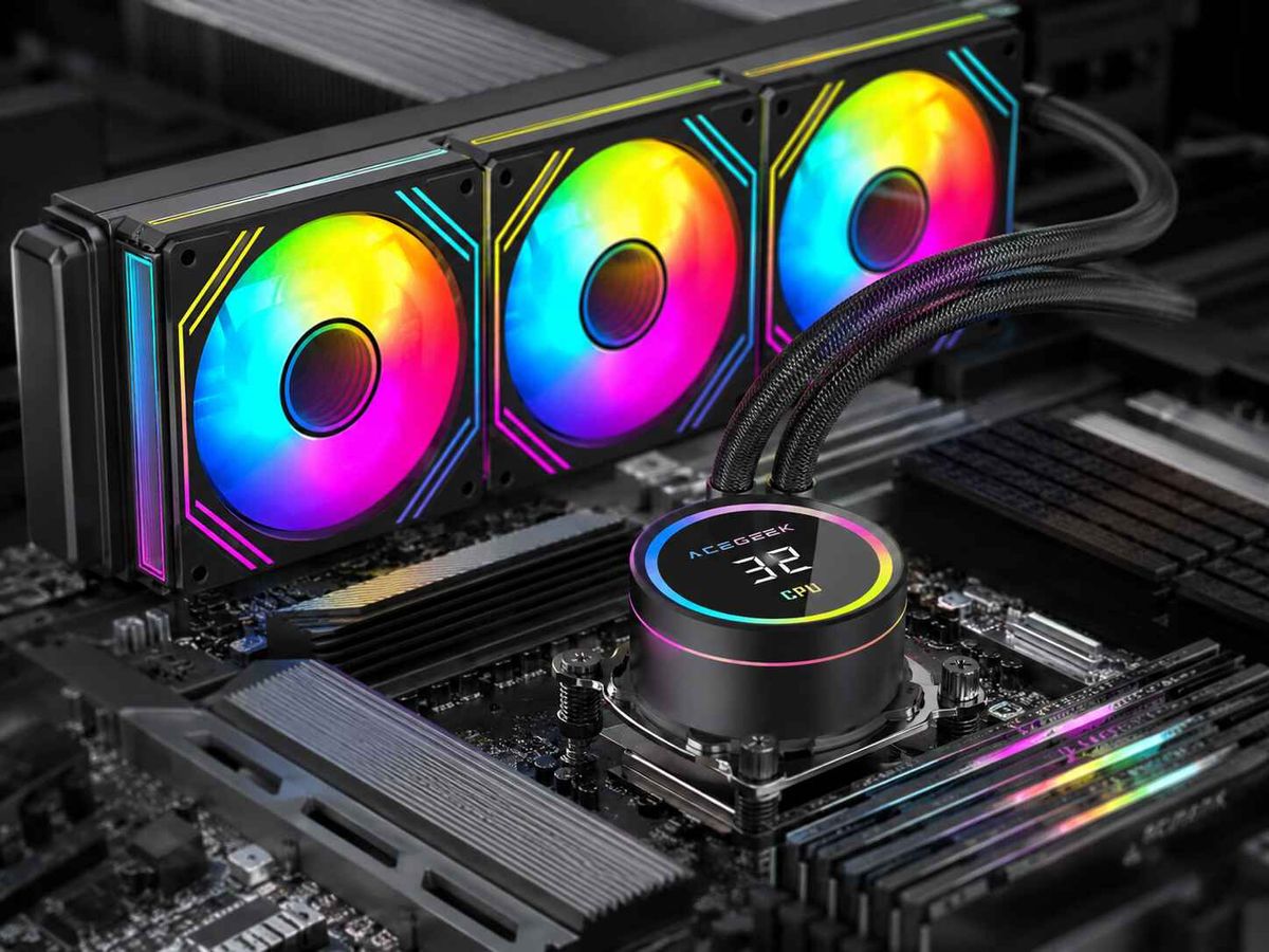
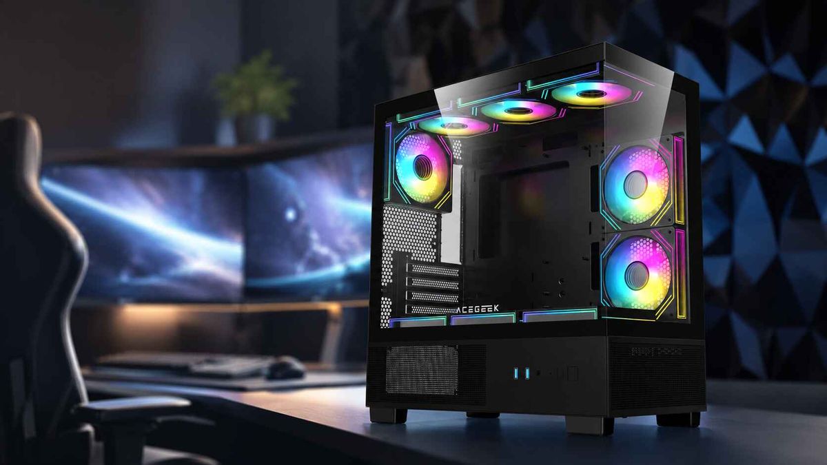
How to Keep Lighting Consistent in Multi-Fan Builds
Consistent RGB fan lighting requires matched lighting hardware, one control authority, verified electrical capacity, identical effect timing, and visual calibration after every fan is installed in its final position.
Bad lighting shows.
When nine fans span the front, side, floor, radiator, and rear exhaust, tiny differences in LED bin, diffuser thickness, cable path, firmware, brightness scaling, and controller timing become obvious because the case turns every mismatch into a repeated pattern.
Why spend heavily on a showcase build only to let one cyan fan expose the whole setup?
The hard truth is that RGB fan synchronization is not primarily an effects problem. It is a system-design problem. Color selection comes last.
Consistent RGB Fan Colors Require More Than a Matching Hex Code
A command such as #FFFFFF, 255,255,255, or “static white” tells the controller what output to request. It does not guarantee that every fan will produce the same visible white.
The final color depends on:
The red, green, and blue LED dies
LED manufacturing bins
The number and placement of LEDs
Diffuser thickness and surface treatment
Fan blade transparency
Controller brightness curves
Supply voltage at each device
Operating temperature
Firmware interpretation
Viewing angle and case reflections
Microsoft acknowledges this directly in its Dynamic Lighting device documentation: colors and brightness can vary slightly between devices from different manufacturers. That admission matters because Microsoft controls the command layer, yet even a common software instruction cannot erase physical differences between products.
NIST documented the deeper manufacturing reason years ago. Its solid-state lighting standards report explains that white LEDs are manufactured across relatively broad chromaticity variations and then separated into bins. Different suppliers historically used different binning systems. Two LEDs sold as “white” therefore need not occupy the same point in color space.
My rule is blunt: the more visible the fans are, the less freedom you have to mix them.
A rear exhaust fan hidden behind dark mesh may tolerate a small color difference. Three side-mounted fans sitting behind clear glass will not.
Choose One Lighting Standard Before Building the Fan Array
Start by separating fan speed control from lighting control. Builders still confuse these two systems, especially when every fan carries two cables.
A typical illuminated PC fan may have:
A three-pin DC or four-pin PWM motor connector
A separate four-pin 12V RGB or three-pin 5V ARGB connector
The motor cable controls blade speed. The lighting cable controls LEDs. One can work while the other remains disconnected or incorrectly configured.
ACEGEEK’s guide to three-pin and four-pin PC fans explains that the fourth motor pin carries the PWM control signal; this has nothing to do with whether the fan uses RGB or ARGB lighting.
12V RGB and 5V ARGB Are Not Interchangeable
ACEGEEK’s RGB versus ARGB guide correctly separates conventional 12V four-pin RGB from addressable 5V three-pin ARGB. Standard RGB drives an entire connected device with one color, while ARGB sends data that can control individual LEDs or groups of LEDs.
Lighting systemTypical connectorControl levelBest useMain risk12V RGBFour pins: 12V, R, G, BOne color across the connected deviceSimple static lightingLimited effects and no individual LED control5V ARGBThree positions: 5V, data, groundIndividual or grouped LED addressingWaves, gradients, synchronized animationsDamage if connected to a 12V headerProprietary RGBBrand-specific plug and controllerDepends on the ecosystemMatched fan packagesLimited cross-brand compatibilityUSB lighting controllerInternal USB plus SATA powerSoftware-managed zones and effectsLarge or mixed lighting systemsSoftware and firmware dependency
Do not force a three-pin 5V ARGB plug onto a four-pin 12V RGB header.
The current MSI MAG B850 Tomahawk Max WiFi III manual explicitly warns that connecting a 5V ARGB device to its 12V JRGB connector will damage the lighting device. This is not a harmless configuration error. It is an electrical mismatch.
So check the motherboard manual before ordering splitters, hubs, or fans. Connector shape is not a substitute for documentation.
Power Math Decides Whether a Multi-Fan RGB Setup Stays Stable
A splitter creates more connection points. It does not create more electrical capacity.
That distinction gets ignored constantly.
The motherboard header or controller still has a maximum voltage, current, wattage, and often a declared LED-count limit. Attaching more sockets merely divides the existing capacity among more devices.
For example, MSI specifies that each JARGB_V2 connector on the cited MAG B850 board supports up to 240 individually addressable LEDs with a maximum rating of 3A at 5V. The same manual recommends using LED devices with matching specifications for the best visual results.
ASUS uses different published limits on some boards. The TUF Gaming B650-Plus product page states that its three Addressable Gen 2 headers support up to 500 Gen 2 LEDs. The point is not that one number is universally better. The point is that motherboard capabilities vary, so generic internet advice such as “one header can run six fans” is irresponsible.
Calculate Current Before Connecting the Hub
Use the lighting-current rating from each fan specification:
Total ARGB current = fan 1 + fan 2 + fan 3 + other illuminated devices
Then leave operating headroom. I normally use at least 20% unless the controller manufacturer specifies another limit.
Here is an illustrative calculation, not a universal fan rating:
Six fans rated at 0.25A each: 1.50A
Nine fans rated at 0.25A each: 2.25A
Nine fans with 20% headroom: 2.70A
Add an illuminated pump or LED strip: the setup may approach or exceed a 3A header
That is where a SATA-powered RGB fan controller hub becomes useful. The motherboard can provide the data signal while the power supply feeds the LEDs through the hub.
But read the hub specification too. A SATA plug does not prove that every port is independently powered or that the controller can deliver unlimited current.
Split Large Builds Into Logical Zones
For eight, nine, ten, or twelve-fan builds, use zones rather than one reckless chain:
Front or side intake zone
Bottom intake zone
Radiator zone
Rear exhaust zone
Pump, block, or case-strip zone
Zones make faults easier to isolate. They also reduce long cable runs and let you correct visible color differences without disturbing every device in the system.
When selecting hardware, compare fans within the same ACEGEEK cooling fan range rather than treating every illuminated 120mm fan as optically identical. The current category includes separate central-light, mirror-style, and motherboard-synchronized ARGB families, each of which will present light differently through glass.
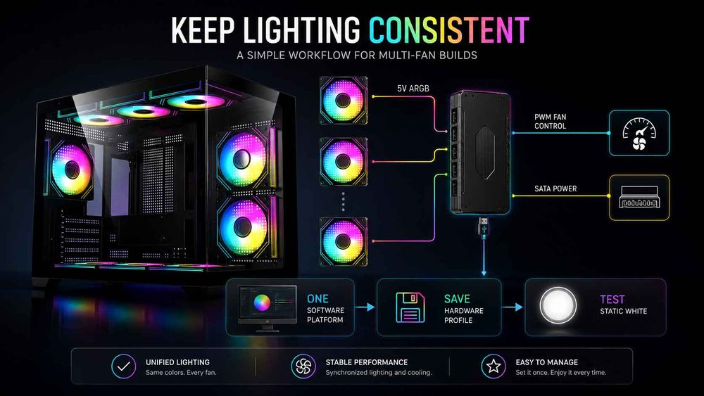
Use One Controller, One Software Platform, and One Master Profile
RGB software conflict is the industry’s dirty secret.
A motherboard utility, Windows service, peripheral suite, game integration, standalone fan controller, and saved hardware profile may all try to control the same device. The result can look like bad hardware:
Colors change after Windows loads
Fans reset after sleep
One zone freezes
Effects stutter
Brightness changes without input
A game replaces the desktop profile
Devices return to rainbow mode during startup
The LEDs are not necessarily failing. They may simply be receiving commands from multiple authorities.
Choose the Control Hierarchy
Pick one of these paths and commit to it:
Control pathBest forWeaknessMotherboard ARGB softwareFans connected directly to board headers or a synchronized hubVendor software can be heavyDedicated hardware controllerLarge matched fan setsMay require proprietary connectorsWindows Dynamic LightingCompatible HID LampArray devices across brandsDevice support remains hardware-dependentStandalone controller buttons or remoteSimple systems without softwareLimited calibration and effect controlThird-party universal softwareMixed-brand systemsCompatibility and update behavior vary
Microsoft’s Windows Dynamic Lighting controls can apply global or device-specific settings to compatible hardware. Microsoft also notes that a foreground application can take control of lighting, which explains why a profile may suddenly change when a game launches.
Dynamic Lighting uses the open HID LampArray standard. Compatible devices can report their LED positions to Windows, allowing effects to account for physical layout instead of treating every product as an unidentified strip. But support must exist in the device firmware or driver. An ordinary ARGB hub does not automatically become a Dynamic Lighting device.
Stop Competing Applications From Launching Together
After choosing the master platform:
Disable lighting control in other applications.
Remove unnecessary RGB programs from startup.
Turn off game integrations during testing.
Update the chosen controller’s firmware.
Reboot and verify the profile from a cold start.
Test sleep and wake behavior.
Save a hardware fallback profile when supported.
Do not install four RGB suites and then blame the fans.
Match the Fans Optically, Not Merely Electrically
Even perfect wiring cannot make two different optical systems look identical.
A fan with LEDs around the outer frame will not match a fan that shines through the hub. A frosted blade scatters light differently from a clear blade. A mirror-frame fan creates reflections that make the same RGB value appear brighter or more saturated.
This is why I recommend keeping all fans visible through the main glass panel within one model family.
For a coordinated build, compare a matched package such as the ACEGEEK Chroma Fan series or the ACEGEEK Prime Fan series, then use the same version for the repeated side, bottom, or radiator positions. Both families are offered as illuminated 120mm fan systems, but their physical designs should still be treated as separate visual groups rather than mixed randomly.
Reverse-Blade and Standard Fans Can Still Look Different
A reverse-blade fan may be useful because it presents the cleaner side while maintaining the desired airflow direction. But its blade curvature, hub structure, supports, and diffuser exposure can change how the LEDs look.
So even when a manufacturer sells standard and reverse versions under the same family, test them together before promising exact color uniformity.
For highly visible showcase builds, I prefer this priority order:
Same model
Same blade version
Same color housing
Same package or production batch where possible
Same controller
Same brightness level
Same physical orientation
The last point sounds obsessive. It is not.
Glass tint, motherboard surfaces, white cables, black radiators, and mirrored panels all alter perceived brightness. A lower fan reflecting against a white case floor may appear stronger than an identical top-mounted fan facing dark mesh.
White Is the Best Test and the Worst Showcase Color
Rainbow effects hide mismatch. Static white reveals it.
Test every zone with these profiles before creating the final effect:
Solid red at 50% brightness
Solid green at 50%
Solid blue at 50%
Neutral white at 25%
Neutral white at 50%
Neutral white at 100%
A slow single-color chase
A slow full-system gradient
Why three primary-color tests? Because a weak or mismatched channel becomes easier to identify. A fan that appears yellow under white may have relatively weak blue output. A magenta cast may indicate weak green output or a calibration difference.
And full brightness is not always best.
Reducing brightness can make slight color differences less obvious, lower LED power consumption, reduce glare against glass, and produce a more expensive-looking finish. Many builds look better at 30% to 60% brightness than at the default 100%.
Temperature and Aging Can Change the Result
The U.S. Department of Energy’s LM-80 LED chromaticity analysis found that LED color-shift rates can change with operating temperature and forward current. One dataset followed warm-white and cool-white modules for up to 20,000 hours under conditions including 75°C or 95°C and currents ranging from 350mA to 1,500mA.
That was not a PC fan test, and I would not pretend otherwise. It demonstrates the physical point: LED color output and long-term color stability are affected by thermal and electrical conditions.
In a gaming PC, that means an older top-radiator fan that has spent years near warm exhaust may eventually differ from a new replacement fan installed beside it. Software calibration can reduce the visual difference. It cannot make aged and new LED packages physically identical.
A Repeatable Workflow for RGB Fan Synchronization
Here is the process I trust for a multi-fan RGB setup.
1. Inventory Every Illuminated Device
Record the exact model and connector for:
Case fans
Radiator fans
Pump block
RAM
GPU lighting
Motherboard lighting
Case strips
Cable extensions
Desk or peripheral lighting
Mark each as 12V RGB, 5V ARGB, USB-controlled, or proprietary.
2. Draw the Lighting Topology
Map which devices connect to:
Motherboard headers
Splitters
Powered hubs
USB controllers
SATA power
Internal USB headers
Do this before cable management. Reopening a finished cable chamber because one data cable was missed is avoidable pain.
3. Verify Every Electrical Limit
Check:
Header voltage
Maximum current
Maximum wattage
Maximum LED count
Hub total capacity
Per-port restrictions
Fan and accessory lighting draw
Use the manual for the exact motherboard revision. Similar model names are not enough.
4. Establish One Master Controller
Decide whether the master is the motherboard, dedicated controller, Windows Dynamic Lighting, or another software platform.
Everything else should follow it or stay disabled.
5. Connect Matched Fans to Matched Zones
Do not randomly distribute different fan models across one visible row. Keep each repeated array consistent.
6. Update Firmware Before Calibration
Update the motherboard utility, hub firmware, and supported fan-controller firmware before investing time in color adjustment. Updates can reset or alter device detection.
7. Create a Diagnostic Profile
Use static red, green, blue, and white at several brightness levels.
Photograph the system from the normal viewing position. Phone cameras exaggerate some differences, but they are excellent at revealing repeated inconsistency.
8. Correct Brightness Before Correcting Hue
A brighter fan can look like a different color even when chromaticity is close. Match brightness first.
Then adjust hue or RGB channels only when the software permits per-zone control.
9. Save the Profile in Hardware
When supported, store the lighting configuration in the controller or device memory. That reduces startup rainbow effects and keeps the build presentable before Windows loads.
10. Test the Full Operating Cycle
Check lighting during:
Cold boot
BIOS
Windows startup
Gaming
Sleep
Wake
Restart
Shutdown
Software updates
A profile that works only after manually opening an application is not a finished configuration.
Fast Diagnosis: What the Lighting Fault Is Telling You
SymptomLikely causeBest first actionOne fan shows the wrong colorDifferent LED order, model, calibration, or damaged channelTest solid red, green, and blueFans reset to rainbow during bootNo hardware-saved profileSave a controller profile or accept firmware defaultColors change after Windows loadsAnother application gains controlDisable duplicate RGB startup servicesFinal fans in a chain are dimmerVoltage drop, excessive load, or weak connectionUse a powered hub and shorten the chainOne zone flickersLoose data connection, overload, or signal issueReseat connectors and test fewer devicesAnimation starts in the wrong placeIncorrect device order or LED countReorder devices in softwareFan spins but has no lightMotor connected, lighting cable disconnectedTrace the separate RGB or ARGB leadLighting works but speed never changesLighting connected, PWM/DC motor control misconfiguredCheck fan header mode in BIOSWhite looks green, pink, or blueLED-bin or optical mismatchCalibrate the zone or replace the mismatched fanEffects freeze after sleepController, USB, firmware, or software-resume issueUpdate firmware and test with one control application
FAQs
How do you sync multiple RGB fans?
To synchronize multiple RGB fans, connect compatible 5V three-pin ARGB devices to one properly powered hub or matched motherboard headers, select one control platform, disable competing lighting applications, confirm the declared LED order, and save one static test profile before applying animated effects across the entire build.
Use solid colors during setup. Animated rainbow effects can conceal wiring errors, LED-order problems, and subtle color differences that become obvious later.
Why do my RGB fans show different shades of white?
RGB fans display different whites because their red, green, and blue LED dies, optical diffusers, manufacturing bins, operating temperatures, brightness curves, and controller calibration are not perfectly identical, so the same digital color value can produce visibly different chromaticity and intensity from one fan model or production batch to another.
Match fan models and production batches where possible. Calibrate brightness before adjusting color channels, since excessive intensity can exaggerate a small white-point difference.
Do I need an RGB fan controller hub?
An RGB fan controller hub is necessary when the number of fans, combined LED current, connector count, cable layout, or synchronization requirement exceeds what the motherboard headers can safely and cleanly support, especially in builds with six to twelve fans, illuminated pumps, light strips, and other addressable devices.
Choose a powered controller with documented input voltage, total output, per-port capacity, software compatibility, and motherboard-sync behavior. Do not buy solely by port count.
Can I mix different RGB fan brands?
You can mix RGB fan brands, but consistent lighting is less predictable because manufacturers may use different LED counts, color calibration, diffuser materials, device ordering, proprietary connectors, and software protocols, which can make static colors look slightly different and animated effects move at different speeds or begin from different physical positions.
Mixing brands is more acceptable in separate visual zones. It is much less forgiving when different fans sit beside one another in a repeated three-fan array.
Is ARGB better than RGB for multi-fan builds?
ARGB is generally better than standard RGB for multi-fan lighting because its 5V data line can control individual LEDs and create synchronized gradients, waves, and zone effects, while 12V four-pin RGB applies one color to an entire connected device or strip and therefore offers less granular visual control.
Standard RGB can still be the better choice for a simple static-color system. More control only helps when the wiring, controller, and software are properly planned.
How many RGB fans can one motherboard header support?
The number of RGB fans that one motherboard header can support is determined by the header’s voltage, maximum current, permitted LED count, and each fan’s lighting power draw, so builders must use the motherboard manual and fan specifications rather than assuming that a splitter with more sockets increases electrical capacity.
Add the current ratings of every connected lighting device and leave reasonable headroom. Use a SATA-powered hub when the calculated load approaches the motherboard header limit.
Build the Lighting Plan Before You Buy the Fans
Do not start with effects.
Start with the exact fan model, number of visible positions, 5V or 12V lighting standard, controller architecture, motherboard limits, software platform, and total current demand. Then choose one visually matched family from the ACEGEEK cooling fan lineup, map each zone, and test static white before completing cable management.
The final rule is simple: same hardware, same controller, same power conditions, same software authority.
Get those four decisions right, and RGB fan lighting becomes predictable. Ignore them, and no amount of clicking through rainbow presets will make a mismatched build look intentional.