How to Daisy-Chain ARGB Fans and Use a Fan Hub
ARGB wiring is badly explained.
Most setup videos show someone joining a row of connectors, plugging the final lead into a motherboard, and celebrating when the fans light up—but they rarely calculate current, separate motor power from LED power, or explain what the hub is actually doing.
That omission matters.
An ARGB fan normally contains two electrical systems:
A fan motor controlled through a 3-pin DC or 4-pin PWM connection.
Addressable LEDs controlled through a 5V 3-pin ARGB connection.
The fan spinning does not prove the lighting is wired correctly. And the LEDs glowing does not prove the motor circuit is safely loaded.
I have a blunt rule: treat cooling and lighting as two separate projects until the final test. Builders who ignore that rule often end up with a fan that spins at full speed, shows the wrong color, disappears from software, or resets to rainbow every time the PC boots.
What Daisy-Chaining ARGB Fans Actually Means
To daisy-chain ARGB fans, you connect the ARGB output of one compatible fan to the ARGB input of the next fan, creating a single lighting path that eventually terminates at a motherboard header, controller, or powered hub.
That sounds straightforward. It is not universal.
Some ARGB fans provide separate male and female 5V connectors for pass-through wiring. Others use proprietary plugs that work only with the included controller. Newer interlocking systems may carry motor power, lighting power, PWM control, and data through one physical bridge.
Never assume two connectors are compatible merely because both have three contacts.
A standard PC ARGB connector normally uses:
5V power
Digital data
Ground
One blocked or missing pin position
A traditional RGB connector normally uses:
12V power
Red
Green
Blue
These are not interchangeable. Connecting a 5V ARGB device to a 12V RGB header can damage the LEDs. MSI explicitly warns in its motherboard documentation that connecting a 5V ARGB strip to its 12V JRGB connector will damage the strip.
That is why the missing pin matters. It is not decorative plastic. It is a warning built into the connector.
Before wiring anything, compare the plug markings:
5V,D, andGnormally indicate ARGB.12V,G,R, andBindicate non-addressable RGB.Arrows on ARGB plugs usually identify the 5V position.
INandOUTlabels define the direction of a true daisy chain.
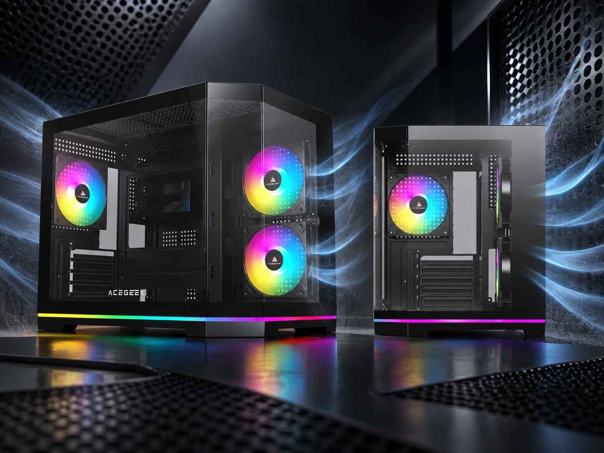
If your fans use ordinary motherboard-sync connectors, the ACEGEEK cooling fan collection provides several ARGB MB Sync options rather than forcing every build into one proprietary software ecosystem. The Chroma ARGB fans, for example, are offered in single-, three-, and five-fan configurations, which makes the planned fan count easier to match before cable routing begins. (ACEGEEK)
Separate the PWM Circuit From the ARGB Circuit
This is where most instructions become dangerously vague.
A fan’s motor connector and lighting connector may travel beside each other, but they perform different jobs and have different electrical limits.
ConnectionTypical plugNormal voltageMain jobCommon failurePWM fan motor4-pin12VPowers motor and controls speedHeader overload or one RPM readingDC fan motor3-pin12VPowers motor through voltage controlIncorrect BIOS modeARGB lighting3-pin with gap5VPowers and addresses individual LEDsFlickering, dimming, or LED damageRGB lighting4-pin12VSets one shared color across the deviceImmediate damage to 5V ARGB LEDsSATA-powered hubSATA inputPSU suppliedAdds independent power capacityMissing SATA connection or poor hub design
PWM Daisy-Chaining Is Not the Same as ARGB Daisy-Chaining
When several PWM fans share one motherboard signal, they generally follow the same speed command. However, a basic splitter usually returns the tachometer signal from only one fan.
That is intentional.
If every fan transmitted an RPM signal through the same sense wire, the motherboard could receive overlapping pulses and report nonsense. A quality splitter or PWM fan hub normally designates one primary port for RPM monitoring.
So when BIOS shows one fan speed for six connected fans, that does not automatically mean five fans are undetected. They may simply be sharing one control signal while only the lead fan reports speed.
The electrical load still counts, though.
For example, suppose six fans are each rated at 0.18A for the motor:
6 × 0.18A = 1.08A
That hypothetical group would exceed a 1A system-fan header. On MSI’s PRO X870-P WIFI, the official manual lists its system-fan headers at 1A and 12W, while its CPU-fan header is rated at 2A and 24W. Those are motherboard-specific limits, not universal numbers.
A passive splitter does not create more power capacity. It merely divides an existing connection.
This is one of the industry’s most persistent half-truths: vendors advertise “supports five fans” while hiding the fact that the motherboard header still has to carry the combined motor current.
ARGB Current Must Be Calculated Separately
Now repeat the process for the LEDs.
Use this formula:
Total ARGB current = Fan 1 LED current + Fan 2 LED current + all other ARGB device currents
Include every device on the circuit:
Case fans
AIO pump lighting
CPU-block lighting
LED strips
GPU support brackets
Reservoir lighting
Case accent panels
Do not calculate from fan count alone. A fan with eight LEDs and a mirror center is not electrically identical to a fan with 24 LEDs around two illuminated rings.
And do not assume that the motherboard’s advertised LED count is the same as its safe electrical limit.
The Header Numbers That Expose Bad Advice
Check the math.
Official motherboard documents show why a universal answer such as “one ARGB header supports six fans” is unreliable, because different boards may share the same 5V voltage while applying different current limits, firmware limits, LED-count rules, and generation-specific behavior.
Why gamble with a motherboard header when the manual gives you the number?
Consider three real manufacturer examples:
Hardware examplePublished ARGB capacityWhat it provesASUS Addressable Gen 2 header3A at 5V; up to 120 Gen 1 or 500 Gen 2 LEDsSoftware generation and electrical capacity are separate limitsMSI MAG X870 Tomahawk WiFi3A at 5V; up to 180 addressable LEDs per JARGB_V2 connectorA 3A header does not guarantee the same supported LED count across brandsCooler Master MasterFan ARGB/PWM HubUp to six ARGB and six PWM connectionsPort count and power distribution depend on the hub design
ASUS’s official support guidance specifies a 3A maximum output at 5V, with support for up to 120 LEDs in Gen 1 mode or 500 in Gen 2 mode. MSI’s MAG X870 Tomahawk WiFi documentation also specifies 3A at 5V, but states a limit of 180 individually addressable LEDs on each JARGB_V2 connector. (ASUS Global)
Same current rating. Different declared LED limits.
That is not a contradiction. It shows that electrical power, signal handling, firmware behavior, and software device mapping are separate issues.
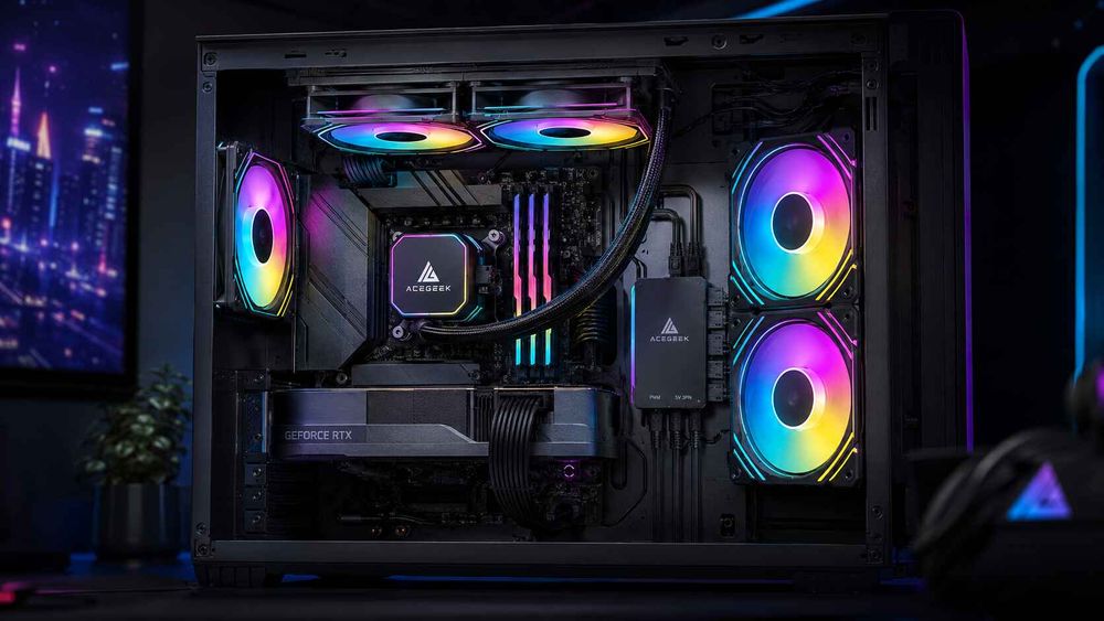
Cooler Master’s MasterFan ARGB and PWM Hub provides six sets of 3-pin ARGB and PWM connections. It is a useful real-world example of why a hub exists: not because daisy-chaining is impossible, but because centralized distribution is cleaner and easier to service in a multi-fan build. (Cooler Master)
My conservative practice is to avoid running any motherboard lighting or fan header continuously at its published maximum. Leaving roughly 20% headroom allows for startup behavior, rating tolerances, extra accessories, and future changes.
That percentage is a planning margin, not a universal motherboard specification. Your manual remains the final authority.
How to Daisy-Chain ARGB Fans Step by Step
1. Shut Down and Disconnect the Power Supply
Turn the computer off, switch the PSU off, and remove the power cable.
Do not install or remove ARGB connectors while the motherboard is powered. MSI specifically tells users to disconnect power before installing or removing addressable lighting hardware.
Press the case power button once after unplugging the system to help discharge residual power.
2. Identify Every Cable Before Connecting Anything
Lay the fans outside the case or place them loosely in their mounting positions.
Find:
The 4-pin PWM motor input
Any PWM pass-through output
The 3-pin 5V ARGB input
Any ARGB pass-through output
Proprietary controller connectors
Direction arrows or 5V markings
Do not force a connector that does not align naturally.
3. Plan the Physical Order
The physical fan order may affect animated effects.
In a simple chain, the controller sends data through the first fan and then onward to the next device. Depending on the fan design and software, a wave may begin at the first connected fan rather than the fan nearest the front of the case.
Plan the order before hiding the cables:
Motherboard or controller → Fan 1 → Fan 2 → Fan 3 → Final fan
For front-mounted intake fans, I normally make the bottom or top fan the first device based on the direction I want the animation to travel. There is no universally correct visual order, but there is an obviously bad time to discover the order: after every cable tie has been tightened.
4. Connect the ARGB Chain
Connect the output of Fan 1 to the input of Fan 2. Continue until the final fan has no downstream device.
Then connect the first fan’s input lead to one of the following:
A motherboard 5V 3-pin ARGB header
A powered ARGB hub
A compatible standalone controller
Align the 5V arrow with the 5V pin.
Never offset the connector by one position. A loose 3-pin housing can sometimes sit incorrectly on a four-position header shell, especially when working in a dark case.
5. Connect the Motor Leads
Connect the PWM leads separately.
For two or three low-current fans, a motherboard header and documented splitter may be sufficient. For larger groups, use a SATA-powered PWM fan hub with a motherboard PWM input.
Connect the hub’s primary or marked port first. That port usually supplies the RPM feedback signal.
The ACEGEEK Prime fan series is listed with an 800–1850 RPM operating range, 60 CFM airflow, 1.90 mm H₂O static pressure, and black or white options. Those motor specifications matter when planning cooling, but you still need the product label or manual for the exact electrical-current calculation. (ACEGEEK)
6. Connect Hub Power Before Booting
A powered hub normally requires SATA power from the PSU.
Without that cable, one of several confusing things may happen:
Nothing works
The fans spin but do not light
Lighting works intermittently
Only the first few ports respond
The motherboard signal cable backfeeds limited control without adequate device power
Route the SATA connection directly to the hub. Avoid stacking it behind high-draw storage devices when a separate PSU cable is readily available.
7. Boot With a Static Test Color
Do not begin with a rainbow animation.
Use solid red, solid green, solid blue, and white. Static colors reveal:
Reversed color channels
A dead LED color
Weak connections
Voltage drop
Fan-to-fan color mismatch
Incorrect device ordering
ACEGEEK’s guide to keeping lighting consistent in multi-fan builds also recommends static-color testing because animated effects can hide wiring errors and color differences. (ACEGEEK)
8. Configure BIOS and Lighting Software
Set motor control correctly:
Use PWM mode for 4-pin PWM fans.
Use DC mode for 3-pin voltage-controlled fans.
Create a gradual fan curve rather than forcing one fixed speed.
Then configure lighting in the motherboard software or controller application.
Common motherboard platforms include:
ASUS Aura Sync through Armoury Crate
MSI Mystic Light
Gigabyte RGB Fusion
ASRock Polychrome RGB
Use one primary lighting application where possible. Multiple programs competing for the same device can cause colors to change after Windows loads, effects to freeze after sleep, or profiles to reset during startup.
Daisy Chain, Splitter, or Powered Fan Hub?
These terms are routinely mixed together, but they describe different hardware behavior.
ARGB Daisy Chain
A true daisy chain passes the connection from one device to the next.
Best for:
Two to four matching fans
Fans with documented pass-through connectors
Clean short cable runs
Builds within the header’s electrical limits
Weaknesses:
A bad connector can affect every downstream fan
Long chains increase voltage-drop risk
Physical order may control animation order
Troubleshooting requires breaking the chain apart
ARGB Fan Splitter
An ARGB fan splitter takes one input and divides it into several parallel outputs.
Most simple splitters mirror the same data signal to every branch. The motherboard may therefore treat several fans as one repeated lighting group rather than separate zones.
Best for:
Identical static colors
Mirrored effects
Two or three nearby devices
Low-current lighting groups
Weaknesses:
No additional power capacity
Limited independent control
Easy to overload when buyers count sockets instead of amperes
Powered ARGB Fan Hub
A powered ARGB fan hub takes electricity from the PSU, usually through SATA, while receiving a lighting-control signal from the motherboard or a dedicated controller.
Best for:
Five or more fans
Panoramic cases with side and bottom fan banks
AIO plus case-fan combinations
Builds with long cable routes
Cleaner cable management
Weaknesses:
Many hubs mirror every output
Some use proprietary connectors
Cheap models may omit clear total-current ratings
A hub can add power without adding independent lighting zones
Here is the hard truth: the best ARGB fan hub is not the one with the most ports. It is the one that publishes its input voltage, total output, per-port limits, PWM behavior, software method, connector type, and RPM-reporting design.
If those numbers are missing, I would not trust the product in an expensive build.
When a Powered Hub Is the Better Choice
I generally move to a powered hub when a build includes five or more illuminated fans, but fan count is only a screening rule. The actual decision comes from electrical load and cable layout.
Use a powered hub when:
The combined motor current approaches the motherboard fan-header limit.
The combined ARGB current approaches the lighting-header limit.
The case requires several intake and exhaust zones.
Daisy-chain cables would cross the visible chamber.
The final fans flicker or appear dimmer.
You are adding an illuminated AIO, strip, or GPU bracket.
You want one serviceable connection point behind the motherboard tray.
A hub is especially useful in larger cases where three side fans, three bottom fans, three top fans, and one rear fan may be spread across four physical zones.
But more fans do not automatically create better cooling.
The airflow path still matters. Before filling every hub port, use the high-airflow PC build guide to decide which mounts should be intake, which should be exhaust, and whether an extra top fan is helping or stealing cool air before it reaches the CPU cooler. (ACEGEEK)
Case size changes the wiring strategy too. An ITX build may benefit from one short daisy chain, while an E-ATX or panoramic chassis often needs a central powered hub. ACEGEEK’s PC case size guide explains how ATX, M-ATX, ITX, and E-ATX layouts differ in fan support and cable-management space. (ACEGEEK)
Common ARGB Fan Problems and the Fixes That Work
SymptomLikely causeFirst actionFans spin but do not lightARGB lead disconnected or wrong hub portTrace the separate 5V lighting cableLights work but speed cannot changePWM lead missing or wrong BIOS modeConnect motor lead and select PWM/DC modeFinal fan flickersVoltage drop, loose connection, or excess loadShorten the chain and test fewer devicesOne fan shows the wrong colorDamaged LED channel or incompatible modelTest solid red, green, and blueAll fans repeat the same effectHub or splitter mirrors one data signalUse separate headers or an independent controllerFan speed reads as zeroWrong hub port used for tach feedbackMove one fan to the primary RPM portLighting resets after Windows startsSoftware conflictDisable duplicate RGB applicationsFans flash during bootController firmware defaultSave a hardware profile when supportedSome ports do nothingSATA power missing or hub capacity exceededVerify hub power and published limitsLEDs stopped working after connection5V device connected to 12V RGBPower down and inspect for damage
Troubleshoot by reduction.
Disconnect every fan except one. Test it directly on the correct header or controller. Then add devices one at a time.
This method feels slow for ten minutes and saves two hours of guessing.
FAQs
Can ARGB fans be daisy-chained safely?
ARGB fans can be daisy-chained only when their connectors and electrical ratings support pass-through operation, the combined lighting current stays below the 5V ARGB header or powered-hub limit, and the combined motor current stays below the PWM header or hub limit stated by the manufacturers.
Check the fan manual for input and output labels before connecting the chain. Keep motor and lighting calculations separate, and never interpret the number of available connectors as proof that the header can safely power every connected device.
What is an ARGB fan hub?
An ARGB fan hub is a central distribution device that connects multiple 5V 3-pin lighting leads and, on combined models, multiple 4-pin PWM motor leads while receiving synchronization commands from a motherboard or controller and drawing additional electrical power from the PSU through SATA.
Some hubs mirror one lighting effect across every port. Others use USB, firmware, or proprietary controllers to create separate zones. Verify whether the product is a powered distributor, an independent controller, or merely a passive splitter before buying it.
How many ARGB fans can be daisy-chained?
The number of ARGB fans that can be daisy-chained is determined by each fan’s LED current, LED count, connector design, data-pass-through support, cable length, and the motherboard or hub’s maximum 5V output—not by a universal fan-count limit advertised across all systems.
Add the specified current draw of every lighting device. Compare the result with the exact header rating in the motherboard manual, leave sensible headroom, and move to a SATA-powered hub when the load approaches the published limit.
Can I connect a 5V 3-pin ARGB plug to a 12V 4-pin RGB header?
A 5V 3-pin ARGB device must not be connected to a 12V 4-pin RGB header because the two systems use different voltages, pin arrangements, and control methods, and applying 12V to electronics designed for 5V can permanently damage the LEDs or their controller chips.
Use only a header marked 5V, ARGB, ADD_GEN2, JARGB, D_LED, or a similar motherboard-specific name confirmed in the manual. Do not rely on connector color, physical proximity, or guesswork.
Why do ARGB fans spin but not light up?
ARGB fans spin without lighting when the 12V motor circuit is connected but the separate 5V lighting circuit is disconnected, reversed, plugged into an unpowered hub, attached to an incompatible controller, or disabled by lighting software, firmware settings, or a damaged ARGB connection.
Trace both cables from the fan. Confirm SATA power at the hub, align the 5V arrow correctly, test one fan directly, and use a solid-color profile before reconnecting the entire group.
Do all fans connected to an ARGB hub show the same effect?
Fans connected to a basic ARGB hub usually display the same synchronized or mirrored effect because the hub distributes one motherboard data signal across multiple output ports, although more advanced USB controllers and proprietary ecosystems may detect devices separately and assign independent effects or zones.
Port count does not equal zone count. Check whether the hub offers independent channel control, per-port LED configuration, or only motherboard synchronization before expecting each fan to behave as a separate software device.
Build the Chain Once, Not Twice
Do not start by plugging every fan into the nearest socket.
First, write down the motor current, ARGB current, LED count, motherboard-header limits, hub limits, cable direction, and intended fan order. Then build one short test chain outside the finished cable-management route.
Once one fan works, add the second. Then the third.
After the full group passes red, green, blue, white, PWM-control, RPM-reporting, sleep-resume, and restart tests, route the wires permanently and secure the connectors.
Review the ACEGEEK ARGB fan range, choose a matching fan set for your required airflow and visual design, and calculate the electrical load before deciding whether your build needs a simple daisy chain, an ARGB fan splitter, or a SATA-powered ARGB and PWM hub.