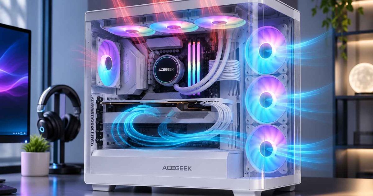
How to Identify Airflow Dead Zones Inside a PC Case
An airflow dead zone is a region inside a PC case where air moves too slowly, or loops back on itself, to carry heat away from the components sitting there. You find one by combining three kinds of evidence: temperature logs from more than one sensor, a visual check of how air actually moves, and a one-variable change that confirms the cause. Fan count and case photos can't show it. For system integrators and OEM case buyers, the issue is concrete. A case can pass a quick benchmark and still leave a GPU, memory, or VRM area with warm, slow air under sustained load. This guide explains where dead zones form, how to test for them, and when one is acceptable.
What Is an Airflow Dead Zone in a PC Case?
For this article, a dead zone is any region of the case where airflow is weak enough, or recirculated enough, that a heat-producing component there runs hotter than the rest of the system would suggest. There are two common forms:
Stagnant pockets. Air barely moves. Heat builds up around components that lie outside the main intake-to-exhaust stream.
Recirculation loops. Air moves, but it is air the system has already warmed, such as GPU exhaust drawn back into an intake path.
Location alone doesn't make a pocket a problem. It matters when a component with a real heat load sits inside it. The IJETT computational fluid dynamics study of fan configuration in gaming desktops simulated two enclosure designs at maximum fan speed. Its conclusion notes high RAM temperatures and blames the difficulty of cooling components oriented awkwardly relative to the air inlet. That is the pattern to look for: a component whose position puts it outside the main stream.
The practical consequence is performance loss. Per Intel's throttling troubleshooting article, processors reduce clock speed when temperature rises above TJ Max (or Tcase), and Intel's fix list includes checking fan operation and air ventilation.
Where Do Dead Zones Usually Form?
These are the locations that ACEGEEK's and Noctua's airflow material point to most often:
The lower GPU intake lane. ACEGEEK's front panel design and PC case cooling guide notes that if a PSU shroud, solid panel section, or cable bundle blocks the lower intake, the graphics card starts recycling warmer internal air.
Under a top-front exhaust fan. A fan placed near the front intake column can lift incoming air toward the roof before it crosses the GPU.
Between opposing fans. Noctua's airflow guide on setup ideas warns that streams meeting head-on create turbulence, hurt cooling, and add noise.
Behind restrictive or narrow intake paths. Glass fronts with thin side slots, dense filters, and decorative trim limit how much air reaches the fans at all.
Pockets outside the main stream. Memory and motherboard areas away from the intake-to-exhaust path may see slow air even when the CPU and GPU look fine.
Downstream of a radiator. A radiator used as intake sends warmed air into the chamber, which can affect GPU and motherboard temperatures.
Panoramic and dual-glass designs deserve a closer look. Their intake often sits at the side and bottom rather than the front, so the usable air path depends on opening placement, GPU orientation, and fan speed. ACEGEEK's guide to side intake fan setup in a panoramic PC case covers those dependencies.
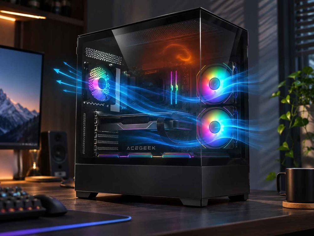
How to Identify Airflow Dead Zones Step by Step
Step 1: Map the intended airflow path
Start on paper, not with software. Mark every fan position, its actual airflow direction, and where air should enter, cross the hot components, and leave. Noctua's guide describes intake and exhaust fans ideally positioned at opposite sides of the case, with a mostly unobstructed flow between them.
Then check each fan's real direction. ACEGEEK's panoramic-case guide advises reading the airflow arrow on the frame or the manufacturer's documentation. It says not to rely on RGB orientation, fan appearance, or rotation direction. Reverse-blade designs make appearance a particularly poor guide.
Mark the heat sources too: GPU, CPU cooler or radiator, VRM area, memory, and storage. Any heat source that falls outside the drawn path is a candidate dead zone.
Step 2: Establish a thermal baseline with more than one sensor
Run a repeatable sustained load with the side panel on, in the configuration users will live with. Record ambient temperature, GPU core, GPU hotspot, CPU package, fan speeds, and clock behavior. ACEGEEK's guide to positive, negative, and neutral case pressure recommends a delta T (component temperature minus ambient) so runs on different days can be compared.
Logging several sensors matters because a change that helps one component can hurt another. ACEGEEK's guide to balancing CPU cooling and GPU airflow makes the same point: builders often optimize the sensor they watch most, usually the CPU, while the GPU hotspot climbs.
Built-in sensors have a blind spot. The CFD paper cautions that the exact locations of motherboard sensors in its validation were unknown, so those readings should be interpreted with caution. If you suspect a pocket near memory or VRMs, a small external probe placed there will tell you more than the board's own reading. This is my engineering recommendation, not a published procedure. Record where the probe sits so the test can be repeated.
Step 3: Visualize the airflow
Temperature logs show the effect. Flow visualization shows the cause. NASA's overview of smoke and tuft flow visualization describes two of the oldest techniques. Smoke can reveal vortices and regions of separated flow and can be dispersed with a hollow wand moved through the flow field. Tufts are short lengths of string whose direction indicates cross-flow, reverse flow, or separation. NASA also says tufts must be light enough to move with the flow without altering it.
Those are wind-tunnel descriptions. Adapting them to a PC case is my own suggestion:
Tufts on light mounts. Place them near suspected pockets, such as behind the GPU, beside memory, and below the PSU shroud. A tuft that hangs limp or flips direction suggests weak or reversed flow. Keep all tufts clear of fan blades.
A smoke source at the intake. Watch whether smoke reaches the GPU intake lane, curls back toward the intake, or lingers. Use a method that leaves no residue on live electronics.
A lightweight strip at passive openings. ACEGEEK describes this as a qualitative check of whether an opening acts as intake or exhaust. It does not measure the pressure difference inside the case.
A handheld anemometer, if available. Spot readings at the same points on every sample turn "looks weak" into comparable numbers. Treat them as relative values unless the instrument and method are controlled.
No single method is conclusive. Smoke shows direction and recirculation but not heat. Tufts show local direction but not speed. Temperature logs show the result but not the path. Use at least two together.
Step 4: Confirm with a one-variable change
A suspected dead zone is only a hypothesis until a single change moves the numbers. Change one thing, repeat the identical load, and compare:
Remove the most recently added fan. If GPU temperature drops or holds, that fan wasn't helping.
Run with the front panel off. ACEGEEK's front-panel article says a one- to two-degree change suggests the panel is acceptable, while five to ten degrees points to an intake restriction. Treat that as a diagnostic, not a final configuration.
Change one fan's speed. The pressure guide recommends adjusting one fan setting at a time. If extra exhaust speed adds noise but changes little, that airflow isn't reaching the problem area.
Compare at similar noise or RPM. A layout that is cooler only because every fan runs at 100 percent isn't a better design.
If the temperature doesn't move after the change, the dead zone either isn't where you thought or isn't what limits performance.
What Causes Dead Zones, and What Does Each Cause Point To?
The cause determines the fix, and a wrong guess wastes money. Here is how each symptom maps to a likely cause:
GPU hotspot rises, CPU is fine, and temperature drops with the front panel off. This points to a restricted intake rather than a pocket behind the GPU. Per ACEGEEK's summary of published tests, swapping a mesh insert for tempered glass changed CPU temperature by only about 1°C in one case with wide side vents and two 200mm fans. In another, removing a restrictive front improved GPU temperature by 10.1°C. These come from different cases and platforms, so they aren't directly comparable.
Temperature barely changes when you add fans. Fan count is probably not the limit. ACEGEEK's explanation of why more fans can increase GPU temperature lists the usual mechanisms: a fan pulling cool air away from the GPU path, streams colliding, recirculating warm exhaust, or a fan behind a restrictive panel.
Intake fans run but airflow at the opening is weak. This could be a fan-to-resistance mismatch. ACEGEEK's guide to airflow fans versus static-pressure fans says airflow-oriented fans suit open paths, while pressure-oriented fans help against radiators, dense filters, and narrow vents. It also says to clean the filter and check for obstruction before swapping fans.
Smoke from the intake curls back or tufts spin. Look for colliding streams or a nearby exhaust fan short-circuiting the path.
Components far from the stream run warm while main sensors look normal. Suspect a pocket. More fans may not fix it, because the CFD paper's conclusion is that an efficient three-fan configuration can outperform a six-fan one by improving flow distribution. That finding comes from a simulation of two enclosure designs at maximum fan speed. It supports "layout over count" as a direction, not as a universal rule.
Case fans stay slow during a GPU-heavy load. The fan curve may be keyed to the CPU. ACEGEEK flags this as inference from how curves work, not a measured result.
When Is a Dead Zone Acceptable?
Not every dead zone needs fixing. Eliminating all of them can mean extra fans, higher noise, and more dust paths, while the affected component may already be well inside its limit.
A workable rule is to treat a dead zone as a defect only if three conditions hold:
A component with meaningful heat output sits in the affected area.
Under worst-case sustained load, that component approaches its published thermal limit or triggers throttling.
A change in airflow path, not just more fan speed, measurably improves it.
If a low-power component sits in a quiet corner and stays far from its limit, the dead zone is cosmetic. If a GPU hotspot or VRM reaches throttling territory in a sample case, it is a design problem worth escalating.
An illustrative scenario, not a real customer case: an integrator tests a glass-front sample with three front fans. Smoke released at the lower intake drifts sideways instead of toward the GPU, and the GPU hotspot climbs while CPU temperature stays moderate. With the front panel removed, the GPU improves sharply. The likely finding is an intake restriction, not a dead zone behind the card, and the fix involves panel geometry rather than a fourth fan.
What Should Buyers Specify Before Validating a Case Sample?
Fan quantity alone says almost nothing about airflow. When requesting samples, writing a specification, or comparing quotes, ask for these:
Fan positions and direction. Which slots are populated, and which are intake or exhaust? Don't assume visible fans are all intake.
Supported fan and radiator sizes per position. This lets integrators change layouts without conflicts.
Intake open area and filter type. Ask for panel design, filter density, and vent layout, not just fan count.
The GPU air path. Can lower-front or bottom intake actually reach the card, or does a PSU shroud or frame block it?
Target hardware. State GPU size and power class, CPU cooler type, and radiator position, since airflow needs differ by configuration.
Fan control method. Identify PWM header count, any fan hub, and which temperature source the default curve follows.
Test conditions for any supplier thermal data. Request the load, ambient temperature, fan speed or noise level, and the sensors used. Without these, numbers can't be compared between cases.
Sensor and probe locations. Ask where each reading was taken, since the CFD paper shows how unknown sensor locations limit interpretation.
Pass/fail criteria. Tie them to the component maker's published limits, not to a single benchmark score. Test more than one sample unit if possible, since variation between units is a reasonable thing to check.
Don't treat supplier capability or lead time as given. Confirm them directly for each project.
Frequently Asked Questions
What is an airflow dead zone in a PC case?
It is a region where air moves slowly or recirculates already-warmed air, so a heat-producing component there runs hotter than the rest of the system suggests. It is a working term, not a formal engineering standard.
How can I find airflow dead zones without special equipment?
Log several temperatures under a repeatable load, then use lightweight tufts or a strip at openings to see local airflow direction, and change one variable at a time. Keep all test material clear of fan blades. This gives qualitative evidence, not measured velocity.
Does a dead zone always mean I need more fans?
No. In published and simulated examples, layout and intake restriction often outweigh fan count. An efficient three-fan layout outperformed a six-fan one in a CFD study of two enclosures. Test whether a path change helps before adding fans.
Can temperature sensors alone reveal a dead zone?
Not reliably. Sensors show the effect at their own location, and their placement may not match the pocket. The CFD paper cautions that motherboard sensor locations were unknown. Combine sensor logs with flow visualization or an external probe.
Is a mesh front panel guaranteed to avoid dead zones?
No. ACEGEEK's front-panel guide says panel area, perforation size, filter layers, and fan spacing matter more than the word "mesh." Mesh is usually the safer thermal starting point, but it still needs verification.
How do I tell whether throttling is caused by airflow?
Check whether clocks drop as temperature approaches the processor's limit, then verify fan operation and ventilation, as Intel's guidance suggests. Repeat the test with one airflow change. If temperatures and clocks improve, airflow was a factor.
What should a buyer ask a supplier for when validating a case?
Ask for fan positions and directions, intake open area, filter type, the GPU air path, the default fan-curve source, and full test conditions: load, ambient temperature, fan speed or noise, and sensor locations. Use these to compare cases fairly.